The Coandă effect
For most commercial vessels, frictional resistance accounts for between 50 and 92% of total hydrodynamic resistance, a figure that has defined naval architecture for generations. Hull-form refinement, low-friction coatings and reduction of wetted surface area have all pushed that figure down, but each successive gain is harder won. As designs approach established practical limits, the engineering community is looking elsewhere.
The regulatory context sharpens the urgency. The Energy Efficiency Existing Ship Index and the Energy Efficiency Design Index are demanding measurable, demonstrable gains. Even a 5-10% reduction in skin friction translates directly into reduced propulsion power demand, lower specific fuel oil consumption and improved headroom against compliance thresholds, figures that fleet operators and designers are watching closely.
Active flow control, techniques that modify boundary-layer behaviour dynamically rather than passively, represents one of the most technically promising avenues remaining. It is in this space that a new approach, based on a well-known but underexploited fluid dynamics phenomenon, is attracting attention.
 |
|---|
The Coandă effect in water
The Coandă effect describes the tendency of a fluid jet to adhere to an adjacent curved or flat surface. The mechanism is well understood in aerodynamics: entrainment of surrounding fluid by the jet creates a localised pressure drop between jet and surface, bending the jet toward the surface and sustaining its attachment. What is less commonly exploited is that the effect operates in liquid flows as well as gaseous ones.
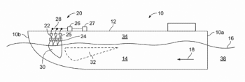
The system described here, protected under US Patent 12,280,854 B2 (2024), directs high-velocity water jets along the hull surface at shallow incidence angles, with jet momentum sufficient to dominate the local near-wall flow field. Under these conditions, the jet adheres to the hull surface and travels with it, the precondition for everything that follows.
The low-pressure region is generated dynamically by the jet, not imposed by hull geometry. That distinction is fundamental.
From surface attachment to vacuum air sheet
As the surface-attached jet travels along the hull, entrainment continuously reduces static pressure in the near-wall region, forming a sustained low-pressure line. This low-pressure region is not a consequence of hull form – it is generated dynamically by the jet–surface interaction, and it persists as long as the jet operates. The distinction matters: it means the air entrainment mechanism is active and controllable, not a fixed function of hull geometry.
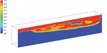
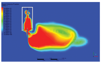
Before crossing the waterline, the free jet naturally entrains atmospheric air through its shear layer. As the jet penetrates the free surface and travels down the hull, it carries this entrained air with it, forming a submerged vacuum air sheet, a continuous, surface-attached layer of air between hull plating and the surrounding water. Computational fluid dynamics (CFD) analysis using volume-fraction contours confirms that this sheet achieves near-complete air coverage (volume fraction approaching 1.0) over substantial hull areas.
 |
|---|
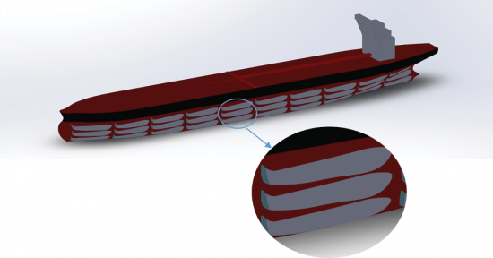
Where the system departs significantly from conventional air lubrication systems is in the character of the air layer itself. Pressurised bubble injection produces buoyancy-dominated bubbles that migrate vertically and disperse away from the hull surface, requiring continuous replenishment and exhibiting inherently inconsistent coverage. The vacuum air sheet produced by jet-induced entrainment is flow-controlled rather than buoyancy-dominated. Because the entrained air moves with the hull-mounted jet, and therefore at vessel speed, it remains attached to the hull surface, resisting the rapid vertical migration that compromises conventional systems.
Pressure mechanics and operational stability
Pressure distribution measurements across the air sheet, perpendicular to the hull, reveal a distinct negative pressure peak near the hull surface, recovering toward ambient conditions further out. This sub-atmospheric core is the entrainment-driven vacuum that holds the sheet in place. On the outer boundary of the air sheet, the vessel’s passage through the water creates a relative flow that acts as a pressure barrier, further resisting disruption of the layer.
Longitudinally, the air sheet exhibits a pressure gradient: lower at the forward end, recovering towards the stern. Importantly, the sheet conforms to hull form contours irrespective of local curvature, which has direct implications for applicability across vessel types. Nozzles can be positioned along bow, midship, bottom, and stern sections; pump configurations can be selectively activated; and jet incidence angles and operating pressures are adjustable to optimise the balance between power input and air-layer behaviour.
Retrofit potential and practical implications
The system’s surface-following character, combined with its independence from hull-integrated air plenums or distribution networks, makes it technically suitable for retrofit. The nozzle assemblies attach to existing hull structure; no cavity machining or major structural modification is required. This is a meaningful practical advantage over cavity-based air lubrication systems, which typically require dry-dock integration during newbuild or major conversion.
Where the air sheet achieves full coverage, the system offers zero skin friction in that region, and the hull is effectively isolated from the surrounding water. The question of net energy benefit, however, requires careful analysis: pump power demand must be offset against propulsive power savings, and this balance is expected to be vessel-type and speed-dependent. Also, when the entire wetted area of a vessel is covered with vacuum air sheets, a feasible objective, then vessel speed can be increased dramatically. The Coandă effect fluid jet system can be fitted to any size vessel.
 |
|---|
|
Figure 3: CFD analysis for the generated air sheet represented by contours of volume fractions, 0 being water and 1 being 100% air |
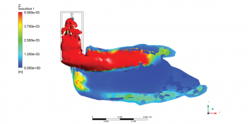 |
| Figure 4: Single jet fixed below waterline contours of volume fraction (left) and isosurface of 0.5 volume fraction (right) |
 |
| Figure 5: Pressure distribution across the air sheet (perpendicular to the hull) showing the negative pressure region |
Open questions and the road ahead
We are transparent about what remains to be characterised. Scaling behaviour from model to full-scale needs to be established systematically. Interaction of the air sheet with surface roughness and biofouling, which alter near-wall turbulence structure, requires dedicated study. Long-term operational stability under varying sea states, trim, and loading conditions represents another gap in the current dataset. However, since the air sheet adheres to the hull, then we believe this system will perform best-in-class when it comes to vessel motions.
The most technically intriguing near-term development is the investigation of pulsed Coandă jets as an alternative to continuous operation. Evidence from related flow-control research suggests that pulsed jets preserve momentum more efficiently and reduce average power consumption, while potentially improving air transport across the air–water interface. Future CFD work is being planned in this area.
As a concept, Coandă-based jet-induced air entrainment occupies a distinct position in the friction-reduction landscape: neither a passive surface treatment nor a conventional pressurised air system, but a form of active multiphase boundary-layer manipulation with its own physical principles. Whether it can deliver net energy gains at operational scale, and at what cost per vessel type, will determine its place in the toolkit available to naval architects navigating an increasingly demanding regulatory environment.
Note:
Khaled M Karmous is the named inventor of US Patent 12,280,854 B2, System and Method for Reducing Drag on the Hull of a Vessel, 2024.
Khaled M Karmous is a mechanical engineer, who graduated from North Carolina State University. He has more than 30 years' experience in oil and gas drilling operations and engineering, and now focuses on developing and advancing practical engineering inventions.
With thanks for the help of Mohamed Hussain, PhD, PE, who specialises in marine hydrodynamics, multiphase CFD, and innovative energy-saving concepts, with a focus on reducing hull drag and improving energy efficiency solutions for the shipping industry.
This article appeared in Features, TNA Mar/Apr 2026
| General | |
| Article Preview Text | For most commercial vessels, frictional resistance accounts for between 50 and 92% of total hydrodynamic resistance, a figure that has defined naval architecture for generations. Hull-form refinement, low-friction coatings and reduction of wetted surface area have all pushed that figure down, but each successive gain is harder won. As designs approach established practical limits, the engineering community is looking elsewhere.
The regulatory context sharpens the urgency. The Energy Efficiency Existing Ship Index and the Energy Efficiency Design Index are demanding measurable, demonstrable gains. Even a 5-10% reduction in skin friction translates directly into |
| Naval Architect Edition | |
| Naval Architect Edition | |
| Article Tags | |
| Article Tags | Hydrodynamics |